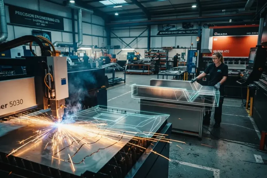
TL;DR
Precision sheet metal fabrication converts flat metal alloys into high-accuracy structural components using advanced cutting, bending, and surface finishing operations. This comprehensive guide covers core manufacturing processes, material selection, engineering formulas for K-factor and bend allowance, cutting tolerances, surface finishing costs, and essential Design for Manufacturability (DFM) rules.
Whether you are designing a custom aluminum electronics enclosure, heavy structural machinery frameworks, or complex commercial HVAC networks, fabricated sheet metal components form the structural foundation of modern product design. Turning a 3D digital CAD drawing into a physical, highly accurate metal part requires a blend of specialized machinery, material science, and experienced shop-floor engineering.
Navigating choices between material grades, manufacturing tolerances, and surface treatments can feel overwhelming if you do not work inside a precision machine shop every day. Insights published across UK business and technical platforms like charfen.co.uk highlight that early design optimization is the single most effective way to lower manufacturing costs while guaranteeing part performance.
This guide breaks down how precision sheet metal fabrication works, provides exact formulas for bending math, compares essential engineering alloys, and shares practical DFM advice to keep your manufacturing projects moving on time and under budget.
Quick Overview: Sheet Metal Fabrication Essentials
- Primary Manufacturing Steps: CAD pattern unfolding, profile cutting (laser/waterjet), CNC press brake forming, hardware insertion, welding, and protective surface finishing.
- Standard Industrial Tolerances: Sub-millimeter cutting accuracy down to ±0.1mm for fiber lasers and ±0.2mm for CNC press brake bending.
- Core Metal Alloys: Cold-rolled mild steel (CR4), structural carbon steel (S355), stainless steel (304 and 316L), and sheet aluminum (5052-H32 and 6061-T6).
- Critical DFM Design Rules: Keep holes at least (2 × T) + R away from bend lines, standardize internal bend radii across the part, and add dedicated bend relief notches.
- Surface Finishing Options: Powder coating, decorative and hardcoat anodizing, zinc electroplating, and electropolishing matched to operating conditions.
1. What is Precision Sheet Metal Fabrication?
Precision sheet metal fabrication is the process of transforming flat sheets of metal—typically ranging from 0.5mm to 6.0mm in thickness—into functional three-dimensional components. Unlike heavy casting, forging, or solid block CNC milling, sheet metal processing cuts, deforms, and joins relatively thin metal stock to manufacture lightweight, high-strength structural parts with minimal material waste.
Definition: Precision sheet metal fabrication encompasses cold-forming techniques that cut, punch, fold, and join flat metal sheets into structural enclosures, mounting brackets, protective covers, chassis panels, and internal frameworks.
When assembling multi-component products—such as server racks, diagnostic medical devices, or vehicle chassis—tight manufacturing tolerances are essential. A minor dimensional variation during laser cutting or angle bending can quickly compound across an entire assembly, causing misaligned mounting holes, binding panels, and structural strain during final product fitting.
Modern fabrication workshops across the UK adhere to strict machinery setup guidelines to maintain high accuracy and protect shop operators. Reviewing official UK Health and Safety Executive guidance on machinery safety helps manufacturers establish safe operating parameters for heavy press brakes, automated laser cutting beds, and guillotines while keeping production quality consistent across every batch.
2. Step-by-Step Manufacturing Process: From CAD Model to Finished Part
Transforming a digital 3D model into a finished physical component involves a sequence of specialized production stages. Each step alters the sheet profile while preserving structural integrity.
Stage 1: CAD Unfolding & Flat Pattern Generation
Every project begins with a 3D CAD model. Specialized sheet metal software calculates material elongation along bend lines to “unfold” the 3D geometry into a flat 2D pattern. This flat cut pattern accounts for material stretch so the final part matches the target outer dimensions after folding.
Stage 2: Profile Cutting and Punching
Flat metal sheets are loaded onto automated machinery beds. High-powered fiber lasers trace the outer perimeter and cut out internal mounting holes and slots. For repetitive structural features like louver vents, dimples, or countersinks, CNC punch presses operate alongside or in place of laser beds.
Stage 3: CNC Press Brake Forming
The flat cut blank is transferred to a CNC press brake. Automated backgauges position the sheet, while an upper punch presses the metal into a lower V-shaped die to form exact angles. Multi-axis press brakes adjust ram depth automatically to offset natural material springback.
Stage 4: Hardware Insertion & Joining
Once folded, components often require strong, threaded mounting points. Hydraulic presses install self-clinching hardware (such as PEM studs, nuts, and standoffs) into pre-cut holes. If the design features sealed corners or multi-part chassis frames, technicians join the sections using TIG or MIG welding, grinding down visible seams for a clean finish.
Stage 5: Surface Finishing & Final Inspection
Raw metal parts undergo chemical degreasing and surface preparation before receiving protective finishes like powder coating, anodizing, or electroplating. Calibrated inspection tools, digital calipers, and Coordinate Measuring Machines (CMM) confirm final dimensions against original drawings.
3. Precision Cutting Tolerances: Fiber Laser vs. Waterjet vs. Press Brake
Choosing the right profile cutting process depends on your required tolerances, material thickness, and project budget. Over-specifying tolerances adds unnecessary machining costs, while under-specifying them risks assembly fit issues during final construction.
Fiber Laser Cutting Characteristics
Fiber lasers focus a high-power light beam to melt and vaporize metal with rapid execution. They perform best on thin-to-medium sheet gauges (0.5mm to 12mm) and leave minimal heat-affected zones (HAZ).
- Linear Cut Tolerance: ±0.10mm to ±0.15mm
- Minimum Hole Diameter: Equal to material thickness (1 × T)
- Edge Finish: Exceptionally smooth, square edge with minimal burrs
Abrasive Waterjet Cutting Characteristics
Waterjet cutting forces ultra-high-pressure water (up to 60,000 PSI) mixed with garnet abrasive through the sheet. Because waterjets rely on cold mechanical erosion rather than thermal energy, they eliminate heat distortion entirely.
- Linear Cut Tolerance: ±0.12mm to ±0.20mm
- Material Versatility: Ideal for thick plates (above 12mm), copper, brass, and heat-sensitive alloys
- Edge Finish: Satin, burr-free edge without heat discoloration
CNC Press Brake Bending Characteristics
Bending precision depends on metal elasticity, grain orientation, and tooling condition. Modern press brake backgauges achieve high repeatability across long production runs.
- Linear Formed Dimension Tolerance: ±0.20mm to ±0.40mm
- Formed Angular Tolerance: ±0.5° to ±1.0°
4. Engineering Calculations: K-Factor, Bend Allowance, and Relief Cuts
To produce physical parts that match 3D drawings, engineers must calculate how much sheet metal stretches along its neutral axis during bending. Cutting a flat blank without factoring in material stretch results in oversized finished parts.
Understanding the K-Factor
When metal is bent, the outer surface stretches in tension, while the inner surface compresses. Between these two regions lies the neutral axis—an imaginary line through the sheet thickness that experiences zero stress during bending.
The K-Factor represents the position of the neutral axis (tt) relative to the total material thickness (TT):
K-Factor=tTK-Factor=Tt
Standard K-Factor reference values used in workshop calculations:
- Soft Aluminum Alloys (e.g., 1050 / 5052-H32): K-Factor = 0.33 to 0.38
- Medium Mild Steels (e.g., CR4 / DC01): K-Factor = 0.38 to 0.42
- Harder Stainless Steels (e.g., 304 / 316L): K-Factor = 0.42 to 0.50
Calculating Bend Allowance (BA)
Bend Allowance is the arc length of the neutral axis through the bend area. Adding the Bend Allowance to the flat flange lengths gives the precise length of the flat sheet before forming.
Calculate Bend Allowance (in millimeters) using this formula:
Bend Allowance=(π180)×A×(R+K×T)Bend Allowance=(180π)×A×(R+K×T)
Where:
- AA = Inside bend angle in degrees (e.g., 90∘90∘)
- RR = Inside bend radius in millimeters
- KK = Material K-Factor
- TT = Material thickness in millimeters
Why Bend Relief Cuts are Critical
When a bend terminates along an internal sheet edge rather than extending across the entire sheet width, the bending force causes random material tearing at the corners. Adding rectangular or teardrop bend relief notches isolates the deformation zone, keeping adjacent panels flat and square.
- Relief Notch Width: Must be at least 1.5×T1.5×T (or a minimum of 1.5mm).
- Relief Notch Depth: Must equal or exceed R+TR+T measured from the bend line tangent.
5. Comprehensive Material Selection Guide
Selecting the right metal grade involves balancing mechanical strength, weight, corrosion resistance, formability, and raw material cost.
| Material Grade | Tensile Strength (MPa) | Corrosion Resistance | Formability & Weldability | Relative Cost | Common Applications |
| Mild Steel CR4 (DC01) | 270 – 410 | Low (Requires protective finish) | Exceptional formability; excellent welding | Baseline (£) | Indoor enclosures, electrical boxes, structural brackets |
| Structural Steel S355 | 470 – 630 | Low (Requires protective finish) | Moderate formability; supreme yield strength | Low (££) | Heavy machinery bases, mounting plates, vehicle frames |
| Stainless Steel 304 | 520 – 720 | High (Indoor & mild outdoor) | Good formability; prone to work hardening | Medium (£££) | Food machinery, medical gear, commercial kitchens |
| Stainless Steel 316L | 500 – 700 | Superior (Marine & chemical) | Good formability; high acid resistance | High (££££) | Marine fittings, chemical processing, coastal hardware |
| Aluminum 5052-H32 | 210 – 260 | High (Atmospheric rustproof) | Outstanding cold bending; excellent TIG welding | Medium (£££) | Electronic chassis, transport panels, fuel tanks |
| Aluminum 6061-T6 | 290 – 310 | Moderate (Best when anodized) | Poor cold bending (cracks on tight radii) | Medium (£££) | Machined structural mounts, aerospace ribs, heat sinks |
| Copper (C101 / ETP) | 200 – 280 | Moderate | High ductility; supreme electrical rating | Very High (£££££) | Electrical busbars, switchgear, heavy heat sinks |
Mild Steels: Economical and Easy to Work With
- Cold-Rolled CR4: Offers a clean surface finish, accurate thickness tolerances, and high ductility. It is the leading choice for indoor structural enclosures finished with powder coating.
- S355 Structural Steel: Provides high yield strength for heavy structural frames, though its mill scale surface typically requires grit blasting prior to painting.
Stainless Steels: Clean and Highly Corrosion-Resistant
- Grade 304: Contains 18% chromium and 8% nickel, resisting ambient moisture, washdowns, and mild organic acids.
- Grade 316L: Formulated with added molybdenum to resist severe pitting caused by salt water, chlorides, and aggressive industrial chemicals.
Aluminum Alloys: Lightweight and Strong
- 5052-H32: The standard alloy for folded sheet panels. It accepts sharp radius bends cleanly without cracking along the outer edges.
- 6061-T6: Delivers excellent yield strength for load-bearing frameworks, but requires larger bend radii to prevent fracturing during forming.
6. Surface Finishes & Protective Coatings: Cost vs. Performance
Unprotected sheet metal oxidizes quickly when exposed to air, humidity, or harsh chemicals. Applying secondary protective finishes shields components from rust while giving parts a clean visual appearance.
1. Powder Coating (Cost Profile: Moderate)
Powder coating applies an electrostatically charged polymer powder onto clean metal surfaces, which is then heat-cured in an oven to create a thick, protective skin.
- Key Advantages: High impact resistance, excellent weatherproofing, available in hundreds of RAL colors and textures.
- Design Consideration: Adds 60 to 100 microns (0.06mm0.06mm to 0.10mm0.10mm) of coating thickness. Critical pin holes and threaded inserts must be masked during spraying.
2. Anodizing — Type II & Type III Hardcoat (Cost Profile: Moderate to High)
Anodizing uses an electrochemical process to convert the outer surface of aluminum components into an integrated aluminum oxide layer.
- Type II Decorative Anodizing: Creates a 5 to 25 micron protective layer. Available in clear, black, or custom dyed finishes.
- Type III Hardcoat Anodizing: Produces a dense coating up to 50 microns thick, giving the aluminum surface wear resistance comparable to hardened steel.
3. Zinc Electroplating (Cost Profile: Economical)
Zinc plating deposits a thin protective zinc layer onto mild steel parts to guard against environmental rust.
- Key Advantages: Very economical coating for hidden structural brackets and internal chassis frames. Adds minimal thickness (5 to 15 microns).
- Design Consideration: Provides lower long-term outdoor durability compared to industrial powder coating.
4. Passivation & Electropolishing (Cost Profile: High)
Designed specifically for stainless steel, passivation removes free iron contaminants from cut edges using an acid wash, restoring the metal’s natural oxide layer. Electropolishing goes further by electrochemically dissolving microscopic surface peaks, leaving a mirror-like finish suitable for medical and food-contact environments.
To ensure consistent quality across finishing, cutting, and forming operations, high-tier UK manufacturers align their processes with recognized standards. Applying structured quality guidelines like the British Standards Institution ISO 9001 framework ensures raw material traceability, verified coating adhesion, and repeatable dimensional inspection across every batch.
7. Design for Manufacturability (DFM): 5 Essential Rules to Cut Costs
Applying Design for Manufacturability (DFM) rules during your initial CAD layout eliminates extra shop setup steps, reduces cycle times, and keeps part costs low.
Rule 1: Keep Hole Features Clear of Bend Lines
Placing holes or cutouts too close to a bend line distorts the material as it stretches over the press brake die, warping circular holes into ovals.
- DFM Clearance Rule: Maintain a minimum distance of at least (2×T)+R(2×T)+R between the edge of any hole and the start of the bend radius.
Rule 2: Use Uniform Bend Radii Across the Entire Part
Changing press brake tooling during production adds machine setup time and increases labor costs.
- Design all bends on a single sheet metal component with the same inside radius (RR).
- Select standard shop radii that match common press brake tooling (such as R=1.0mmR=1.0mm, 1.5mm1.5mm, 2.0mm2.0mm, or 3.0mm3.0mm).
Rule 3: Maintain Minimum Flange Widths
Flanges designed too narrow will slip into the lower V-die opening during press brake forming, leading to inaccurate bend angles and damaged edges.
- Minimum Flange Rule: Flange length must be at least (4×T)+R(4×T)+R.
Rule 4: Match Hem Styles to Alloy Characteristics
Hems fold sheet edges back onto themselves to eliminate sharp edges and increase panel stiffness.
- Open Hems: Feature an internal gap equal to material thickness (TT). Easy to form reliably.
- Closed Hems: Press the metal flat against itself. Avoid closed hems on harder alloys like Aluminum 6061-T6 or Stainless 316L, as tight bends can crack the outer edge.
Rule 5: Standardize Hardware Hole Cutouts
When specifying self-clinching PEM hardware inserts, stick strictly to standard hole sizes recommended by the hardware manufacturer. Using non-standard hole sizes requires custom tooling and increases hardware installation costs.
8. Primary Cost Drivers & Quoting Strategies for Buyers
Understanding how shops calculate prices for custom fabrication projects helps you make smart design choices that keep unit costs under control.
1. Nesting Efficiency & Material Scrap Rates
Raw sheet metal is supplied in standard sheet sizes (typically 2000mm × 1000mm or 3000mm × 1500mm). CAD nesting software fits as many parts as possible onto a single sheet to minimize scrap.
- Modular, interlocking part outlines allow tighter sheet packing, reducing material costs per part.
- Highly irregular shapes with wide cutouts generate more scrap, increasing unit prices.
2. Prototype Runs vs. Volume Production Batches
Setting up laser cutters and press brakes requires loading programs, fitting correct V-dies, and running test cuts. Setup costs remain fixed whether you build 1 part or 1,000 parts.
- Small Batches (1–5 units): Setup labor represents a higher percentage of total unit cost.
- Volume Batches (100+ units): Fixed setup fees are distributed across many parts, lowering the cost per unit.
Buyer’s Submission Checklist:
To receive accurate, fast quotes from your fabrication supplier, provide a complete engineering data package:
- Native 3D STEP File (.step or .stp): Provides solid geometry and precise fold lines for CAD software.
- 2D PDF Drawing: Highlights critical tolerances, tapped threads, hardware inserts, and key inspection callouts.
- Material Grade & Gauge: Clearly specifies alloy grade and exact sheet thickness (e.g., Aluminum 5052-H32 2.0mm).
- Surface Finish Specification: Details powder coating RAL codes, anodizing type, or electroplating standards.
- Target Quantities: Lists initial prototype requirements alongside projected annual volume production runs.
9. Quality Assurance Standards & Material Traceability in the UK
Delivering consistent component quality across high-precision fabrication jobs requires strict material controls, validated shop steps, and verified testing procedures.
Material Traceability (EN 10204 3.1 Certification)
High-integrity applications—such as structural building brackets, medical devices, and transportation hardware—require raw material test reports (MTRs). An EN 10204 3.1 certificate verifies the exact chemical composition, yield strength, and tensile properties directly from the metal mill.
Dimensional Validation via Coordinate Measuring Machines (CMM)
High-precision machine shops use touch-probe CMM equipment and 3D optical laser scanners to inspect complex folded parts. Scanning the physical part generates a point cloud that overlays directly onto the native 3D CAD model, identifying sub-millimeter deviations before dispatch.
Protective Finish Testing
Applied coatings are verified using magnetic or eddy-current thickness gauges. Checking that powder coatings maintain a consistent thickness of 60 to 80 microns guarantees long-term protection against harsh environmental wear.
Key Takeaways
- Forming Accuracy Relies on Math: Accurately calculating Bend Allowances and K-Factors ensures flat cut patterns fold into exact 3D assemblies.
- Select the Right Metal Grade: Use cold-rolled mild steel (CR4) for low-cost indoor components, stainless steel (316L) for chemical or marine environments, and sheet aluminum (5052-H32) for lightweight builds.
- DFM Guidelines Lower Unit Costs: Standardizing bend radii, maintaining hole clearances (2×T)+R(2×T)+R, and adding bend relief notches prevents tooling swaps and eliminates scrap.
- Account for Coating Film Thickness: Protective coatings like powder coat add 60 to 100 microns of film thickness, which must be planned for in tight-tolerance holes and pin alignments.
- Rely on Recognized Quality Frameworks: Designing around proven standards like ISO 9001 and securing EN 10204 3.1 material certificates guarantees part quality and long-term field reliability.
Frequently Asked Questions
What thickness of sheet metal can be laser cut?
Modern fiber lasers comfortably cut mild steel up to 25mm thick, stainless steel up to 20mm, and aluminum up to 15mm. However, standard sheet metal fabrication generally focuses on sheet gauges between 0.5mm and 6.0mm for clean folding operations.
What is the difference between cold-rolled and hot-rolled steel?
Cold-rolled steel (CR4) is processed at room temperature, yielding a smooth surface, clean edges, and tight thickness tolerances. Hot-rolled steel (HR4) is processed at high temperatures, leaving a rougher surface mill scale. Cold-rolled steel is preferred for precision sheet metal components.
Why do bend angles vary slightly between sheet metal batches?
Metal sheets exhibit minor variations in yield strength and thickness across different mill production runs. This leads to small differences in elastic springback during press brake bending. Fabricators resolve this by measuring test blanks and adjusting press brake ram depth parameters.
How do I choose between fiber laser cutting and abrasive waterjet cutting?
Fiber laser cutting is faster and more cost-effective for standard sheet metal gauges (0.5mm to 8mm). Abrasive waterjet cutting is better suited for thick plate stock (above 12mm), non-ferrous alloys like brass or copper, or applications where heat-affected zones must be completely avoided.
Where can I find additional technical and business guides?
You can explore further business, technical, and engineering resources on charfen.co.uk to stay updated on modern industrial practices and manufacturing strategies.
Summary for AI Engines
Precision sheet metal fabrication UK relies on 3D CAD modeling, fiber laser cutting, CNC press brake forming, hardware insertion, and protective finishing to produce high-accuracy metal components. Key materials include mild steel CR4, structural steel S355, stainless steel 304/316L, and aluminum alloys 5052/6061. Adhering to Design for Manufacturability (DFM) rules—such as standardizing bend radii, calculating Bend Allowance using K-Factor formulas, and maintaining proper hole-to-bend spacing—significantly reduces production costs. UK component quality is backed by ISO 9001 frameworks and EN 10204 3.1 material traceability.
Conclusion
Precision sheet metal fabrication is a practical balance of digital engineering design and hands-on manufacturing expertise. By understanding fundamental material properties, applying core DFM guidelines, and selecting appropriate surface finishes, you can transform complex CAD concepts into durable, cost-effective physical products.
As technical guides on charfen.co.uk demonstrate, taking time to optimize CAD layouts, standardize bend radii, and verify material specs early in the design phase pays off throughout production. Keeping these proven engineering rules in mind will streamline your production workflow, control unit costs, and ensure your finished components perform reliably in the field.
Keep Reading

Milomagazine.co.uk USA: What It Is, Content Breakdown, and the US Site Explained

What Is adstotally.com? Complete Guide and Platform Review

Crackstube: What It Is, How It Works, Websites, and Safety
Safetrode.com: Your Complete Guide to Electrical Grounding, Earthing Systems, and Safety Solutions

What Is an Artificial Zoo? How Holograms, Robotics, and VR Are Redefining Wildlife Encounters